Unity QSD/QSE Software Defined Radio
Updated 20140331
THIS PROJECT IS SUSPENDED AFTER A DEATH IN THE FAMILY, AND PRIORITY ANTENNA WORK.
Why consider doing a QSD/QSE radio when DDC/DUC is superior? Digitising at 100MHz and processing is still expensive in money and power consumption. For example, mixing this and this would be nice but beyond what single amateurs can do.
The previously developed Mobo v4.3 system has a lot of potential for making a multi-band HF transceiver. The basic technology of it is sound, but there are some things that can be improved. I considered the needs of these projects with the hope of some degree of “unity” or compatibility:
Android based tablets are advancing at an amazing rate. Some newer ones support USB sound cards. This would be an ideal back end processing for a black box rig. Like an Elecraft KX3 without the controls or display, but with everything on screen.
Eventually I intend to make a transceiver version, but have to start with a proof of concept board. The circuit diagram is done and initial build/test has commenced. Details of the basic receiver are at the bottom of this page, but first a summary of design process...
Redesign Time!
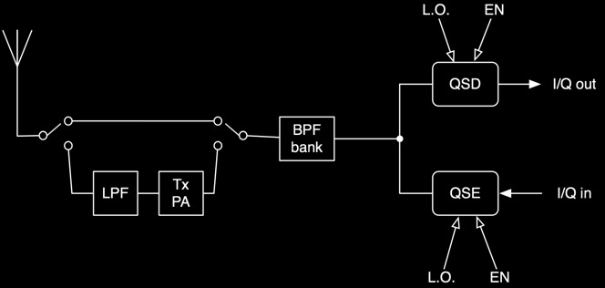
There’s no point in just re-laying the Mobo V4.3 circuit to a 4 layer PCB, a lot of compromises would result. There is nothing for it but a complete redesign, which gives the chance to update everything. Proposed signal path:
Analog Multiplexers and Switches
The Mobo V4.3 has terrible front end loss of ~5dB. Identifying some types of RF switch, I made a test board to compare 74CBT3251 vs. FSA4157 vs. SKY13290-313LF.
Strangely the Mobo V4.3 designers didn’t spot the fact (FST type) bus switches biassed at mid-rail have limited signal range. The FSA4157 is a CMOS switch that passes a rail-rail signal. That device turned out to be poor for RF signals, but its relative the FSA3157 is much better. I measured a loss of 0.33dB at 30MHz with the test board. The bus switch (74CBT3251) was 0.46dB. The SKY13290-313LF was slightly better, but I am wary of using pHEMT devices at low frequencies.
An alternative is PIN diodes which have bias current requirements, and need DC blocking which complicates everything. I found PIN diodes could give lower losses, but over a limited frequency range. With PIN diodes there would be a lot of small extra and fiddly parts.
With a moment of inspiration, it’s clear that something like the ADG708 from Analog Devices is an economical low-part count solution. The channel capacitance of those switches is high, but the capacitance can be absorbed in the filter circuits. This technique has a limit around 30MHz, because at 50MHz the impedance drops to about 15ohms, so the inductor Q causes larger losses. A report on calculating filter values to absorb capacitance is here.
Preamplifier
With reduction in switching loss and mixer noise, the bands up to 21MHz will not require any pre-amplification. A problem with preamps in the proposed architecture is they have to be switched in/out. This means two extra switches for all bands, which cannot be avoided. A suitable preamp circuit is tested elsewhere on this site. The receiver only test board will have no preamp.
Mini-Filters
The filter boards are too small to accept bigger toroids than T37. Small toroids limit dynamic range, and sometimes Q factor. Board space for filter slots to be increased slightly for T50 toroids, with the same connector layout (8x2) as the MoBo V4.3. Hand wound toroids are a right royal pain. Replacing some of those with ready wound inductors looks feasible. Coilcraft produce a nice line of ready wound coils.
Designing PA3AKE style filters is easy with ELSIE software. Choose “mesh capacitor coupled” design. Its clear from simulations in ELSIE and data from Micrometals that mix -6 (carbonyl SW) is not optimum for the critical bands above 20MHz. Mix -10 (carbonyl W) will help. ‘Q’ factor above 150 reduces the losses by several tenths of a dB. I did some testing with -6 mix at 21MHz and 28MHz and losses of ~0.5dB were disappointing, the -10 should be better.
The ‘Q’ factor of small ceramic capacitors of often not very good. There are RF rated type available, often in the odd 1111 size. Some clue as to the ‘Q’ of standard grades is given by Murata’s SimSurfing tool.
Mixer Redesign
The 74AC74 / FST3253 / LT6231 combination as used on Softrock boards is a cheap, minimal component and easy to solder solution. After reviewing a lot of QSD designs I decided to use a modified version of original double balanced Tayloe QSD.
The original Softrock mixer is single balanced, but Flexradio use a balanced design. The basic concept of the QSD has advantages over any other circuit for the task. I looked at combinations of other H-mode designs but the many benefits of the QSD make it a no-brainer choice to stick with. With simplicity and low-cost in mind it is worth revisiting the Tayloe QSD.
I spent a long time looking at alternatives to the 4:1 bus switches, but found nothing really better. The best combination of signal range, cost, and switching speed is probably the TS3A5017 from TI.
In the 10 years since the Dan Tayloe patent and “SDR for the masses” several variants on the QSD were published. Flex have two patents, notably US20110443286. The inventive step is including analog switches in an op-amp feedback loop. Their patent can be implemented using two dual quad switches, and is claimed to have huge dynamic range and near zero conversion loss. This is excellent but high risk. The amplifier requirements are for wide bandwidth and the circuit is unproven. I did a Simulation on QSD designs and modified the older design.
The amateur research par excellence on switching mixers is here, and recommends a squarer on the I/Q clocks. I have the NC7WZ04 (Fairchild Semi) as a buffer. On transmit the Softrock uses a double balanced mixer. The transmitter section of the Softrock boards can be done with several fewer parts, and again this simulates fine.
Other Mobo V4.3 Issues
I2C bus noise has been a problem for builders of the MoBo 4.3 system. I found it can be reduced by using ferrite beads in line, and a capacitor (~100pF) on the clock line. With the controller off board, I2C lines are exposed to static damage. It would be nice to include a transient protection device which has some capacitance to kill both problems. The Elecraft KX3 has 100pF capacitors on the I2C lines.
I intend to support the SDR-Widget as a controller. It would be possible to program similar devices to do “Mobo control” as described in the I2C interfacing document.
I found USB isolation made no difference to the performance of my MoBo system. In fact the ADuM1251 generated noise. Using short and solid grounding between the Softrock mixer and the soundcard (SDR-widget), together with an electrically quiet laptop PC, solved more noise problems than any amount of USB isolation.
Analog Devices tout a lack of EMC issues in advertising, but for the 3 - 30MHz range this is not true. An alternative is Texas Instruments (e.g. ISO7231) capacitive isolators, but the nature of signals they generate to cross the isolation barrier is not clear. The devices are also shockingly expensive and need a lot of external parts.
Unity Basic Receiver Design
After several years of messing about I decided to make a new receiver to supersede my Mobo V4.3 system. The board is a proof of concept and not a complete design, though it should function as a good receiver to replace the old one. If it works the next step is to make a transceiver.
The receiver input starts with a high pass filter with -3dB point of 1.5MHz. This reduces large MW broadcast signals, and the diode protects from discharges. Following is the FSA3157 switch, put in for test purposes. The switching between 2 inputs is not really important and just really there for the sake of it.
The simplicity of the filter bank is seen with two ADG708 switches and plug-in filter boards. Using the idea of absorbing channel capacitance in the filter circuits, a low parts count is achieved. Unfortunately anyone with Mobo 4.3 filters already made will find the higher frequency ones don’t work.
Bias point of the switches is set at about 2.0V, which will be subject to experimentation for least signal loss. A basic first attempt at measuring insertion loss up to the QSD input follows, and this will look better when properly compensated:
As described above, the QSD stage is quite radical, and has options for balanced or unbalanced output. There are more op-amps in the circuit than the Softrock version, but this will perform better. The LT6237 is an improved LT6231 and the cheapest 1.1nV/Hz low noise op-amp available. The balanced output is ideal for driving a balanced 24-bit ADC directly. When used balanced, one of the dual op-amps is not fitted. Overall fewer op-amps are in the chain when driving something like an AK5394 as used in SDR-widget directly.
Page 2 of the circuit is basically a subset of the Mobo V4.3 interfacing parts. The ADC and current sensor are not included. I did include the temperature sensor because it may be useful for measuring the temperature of the Si570 oscillator. Parts for suppressing I2C noise are included. The clock buffers are shown bottom right.
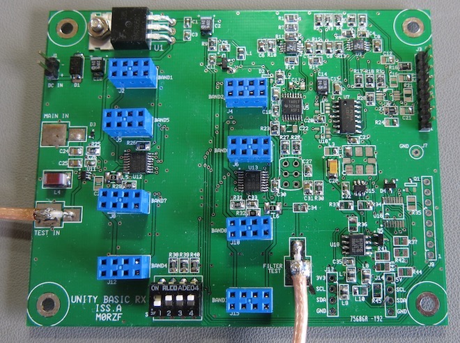
The I2C I/O port has been changed to the PCA9554 because its smaller and lower cost than the original PCF8574. A software change (in PCF8574.c of the SDR-widget code) is needed to drive the PCA9554. A picture of the initial build follows:
Updated 20140331
THIS PROJECT IS SUSPENDED AFTER A DEATH IN THE FAMILY, AND PRIORITY ANTENNA WORK.
Why consider doing a QSD/QSE radio when DDC/DUC is superior? Digitising at 100MHz and processing is still expensive in money and power consumption. For example, mixing this and this would be nice but beyond what single amateurs can do.
The previously developed Mobo v4.3 system has a lot of potential for making a multi-band HF transceiver. The basic technology of it is sound, but there are some things that can be improved. I considered the needs of these projects with the hope of some degree of “unity” or compatibility:
- Motherboard V4.3
- Softrock RxTx V6.3
- SDR-Widget interface
- QtRadio/GHPSDR3 software
- PowerSDR-IQ software
- USB2SDR interface
- SDR2GO interface
- SDR# software receiver
- SDR-Radio software(?)
- DG8SAQ/PE0FKO firmware
- SDR-Cube hardware
Android based tablets are advancing at an amazing rate. Some newer ones support USB sound cards. This would be an ideal back end processing for a black box rig. Like an Elecraft KX3 without the controls or display, but with everything on screen.
Eventually I intend to make a transceiver version, but have to start with a proof of concept board. The circuit diagram is done and initial build/test has commenced. Details of the basic receiver are at the bottom of this page, but first a summary of design process...
Redesign Time!
There’s no point in just re-laying the Mobo V4.3 circuit to a 4 layer PCB, a lot of compromises would result. There is nothing for it but a complete redesign, which gives the chance to update everything. Proposed signal path:
Analog Multiplexers and Switches
The Mobo V4.3 has terrible front end loss of ~5dB. Identifying some types of RF switch, I made a test board to compare 74CBT3251 vs. FSA4157 vs. SKY13290-313LF.
Strangely the Mobo V4.3 designers didn’t spot the fact (FST type) bus switches biassed at mid-rail have limited signal range. The FSA4157 is a CMOS switch that passes a rail-rail signal. That device turned out to be poor for RF signals, but its relative the FSA3157 is much better. I measured a loss of 0.33dB at 30MHz with the test board. The bus switch (74CBT3251) was 0.46dB. The SKY13290-313LF was slightly better, but I am wary of using pHEMT devices at low frequencies.
An alternative is PIN diodes which have bias current requirements, and need DC blocking which complicates everything. I found PIN diodes could give lower losses, but over a limited frequency range. With PIN diodes there would be a lot of small extra and fiddly parts.
With a moment of inspiration, it’s clear that something like the ADG708 from Analog Devices is an economical low-part count solution. The channel capacitance of those switches is high, but the capacitance can be absorbed in the filter circuits. This technique has a limit around 30MHz, because at 50MHz the impedance drops to about 15ohms, so the inductor Q causes larger losses. A report on calculating filter values to absorb capacitance is here.
Preamplifier
With reduction in switching loss and mixer noise, the bands up to 21MHz will not require any pre-amplification. A problem with preamps in the proposed architecture is they have to be switched in/out. This means two extra switches for all bands, which cannot be avoided. A suitable preamp circuit is tested elsewhere on this site. The receiver only test board will have no preamp.
Mini-Filters
The filter boards are too small to accept bigger toroids than T37. Small toroids limit dynamic range, and sometimes Q factor. Board space for filter slots to be increased slightly for T50 toroids, with the same connector layout (8x2) as the MoBo V4.3. Hand wound toroids are a right royal pain. Replacing some of those with ready wound inductors looks feasible. Coilcraft produce a nice line of ready wound coils.
Designing PA3AKE style filters is easy with ELSIE software. Choose “mesh capacitor coupled” design. Its clear from simulations in ELSIE and data from Micrometals that mix -6 (carbonyl SW) is not optimum for the critical bands above 20MHz. Mix -10 (carbonyl W) will help. ‘Q’ factor above 150 reduces the losses by several tenths of a dB. I did some testing with -6 mix at 21MHz and 28MHz and losses of ~0.5dB were disappointing, the -10 should be better.
The ‘Q’ factor of small ceramic capacitors of often not very good. There are RF rated type available, often in the odd 1111 size. Some clue as to the ‘Q’ of standard grades is given by Murata’s SimSurfing tool.
Mixer Redesign
The 74AC74 / FST3253 / LT6231 combination as used on Softrock boards is a cheap, minimal component and easy to solder solution. After reviewing a lot of QSD designs I decided to use a modified version of original double balanced Tayloe QSD.
The original Softrock mixer is single balanced, but Flexradio use a balanced design. The basic concept of the QSD has advantages over any other circuit for the task. I looked at combinations of other H-mode designs but the many benefits of the QSD make it a no-brainer choice to stick with. With simplicity and low-cost in mind it is worth revisiting the Tayloe QSD.
I spent a long time looking at alternatives to the 4:1 bus switches, but found nothing really better. The best combination of signal range, cost, and switching speed is probably the TS3A5017 from TI.
In the 10 years since the Dan Tayloe patent and “SDR for the masses” several variants on the QSD were published. Flex have two patents, notably US20110443286. The inventive step is including analog switches in an op-amp feedback loop. Their patent can be implemented using two dual quad switches, and is claimed to have huge dynamic range and near zero conversion loss. This is excellent but high risk. The amplifier requirements are for wide bandwidth and the circuit is unproven. I did a Simulation on QSD designs and modified the older design.
The amateur research par excellence on switching mixers is here, and recommends a squarer on the I/Q clocks. I have the NC7WZ04 (Fairchild Semi) as a buffer. On transmit the Softrock uses a double balanced mixer. The transmitter section of the Softrock boards can be done with several fewer parts, and again this simulates fine.
Other Mobo V4.3 Issues
I2C bus noise has been a problem for builders of the MoBo 4.3 system. I found it can be reduced by using ferrite beads in line, and a capacitor (~100pF) on the clock line. With the controller off board, I2C lines are exposed to static damage. It would be nice to include a transient protection device which has some capacitance to kill both problems. The Elecraft KX3 has 100pF capacitors on the I2C lines.
I intend to support the SDR-Widget as a controller. It would be possible to program similar devices to do “Mobo control” as described in the I2C interfacing document.
I found USB isolation made no difference to the performance of my MoBo system. In fact the ADuM1251 generated noise. Using short and solid grounding between the Softrock mixer and the soundcard (SDR-widget), together with an electrically quiet laptop PC, solved more noise problems than any amount of USB isolation.
Analog Devices tout a lack of EMC issues in advertising, but for the 3 - 30MHz range this is not true. An alternative is Texas Instruments (e.g. ISO7231) capacitive isolators, but the nature of signals they generate to cross the isolation barrier is not clear. The devices are also shockingly expensive and need a lot of external parts.
Unity Basic Receiver Design
After several years of messing about I decided to make a new receiver to supersede my Mobo V4.3 system. The board is a proof of concept and not a complete design, though it should function as a good receiver to replace the old one. If it works the next step is to make a transceiver.
The receiver input starts with a high pass filter with -3dB point of 1.5MHz. This reduces large MW broadcast signals, and the diode protects from discharges. Following is the FSA3157 switch, put in for test purposes. The switching between 2 inputs is not really important and just really there for the sake of it.
The simplicity of the filter bank is seen with two ADG708 switches and plug-in filter boards. Using the idea of absorbing channel capacitance in the filter circuits, a low parts count is achieved. Unfortunately anyone with Mobo 4.3 filters already made will find the higher frequency ones don’t work.
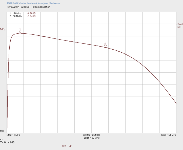
Bias point of the switches is set at about 2.0V, which will be subject to experimentation for least signal loss. A basic first attempt at measuring insertion loss up to the QSD input follows, and this will look better when properly compensated:
As described above, the QSD stage is quite radical, and has options for balanced or unbalanced output. There are more op-amps in the circuit than the Softrock version, but this will perform better. The LT6237 is an improved LT6231 and the cheapest 1.1nV/Hz low noise op-amp available. The balanced output is ideal for driving a balanced 24-bit ADC directly. When used balanced, one of the dual op-amps is not fitted. Overall fewer op-amps are in the chain when driving something like an AK5394 as used in SDR-widget directly.
Page 2 of the circuit is basically a subset of the Mobo V4.3 interfacing parts. The ADC and current sensor are not included. I did include the temperature sensor because it may be useful for measuring the temperature of the Si570 oscillator. Parts for suppressing I2C noise are included. The clock buffers are shown bottom right.
The I2C I/O port has been changed to the PCA9554 because its smaller and lower cost than the original PCF8574. A software change (in PCF8574.c of the SDR-widget code) is needed to drive the PCA9554. A picture of the initial build follows: