Updated 20181230
My main interest in ham radio is small antennas. It’s easy to make large antennas work, just a matter of bucks, trucks and real estate. Small antennas are an area open for experimentation especially at lower frequencies. To keep the page concise I must assume the reader has a basic knowledge of radio and electronics, to the level of amateur radio exams. This page has such accurate measurements as I can take, to back up many years of experience in testing EH and similar designs.
Background
Those familiar with EH Antennas can scroll down to the next green heading, as this section gives background information unrelated to my own tests. Search for “EH antenna” and you will find a lot of information on the Internet. A picture of an EH antenna follows.
It’s two copper or aluminium cylinders wrapped around a plastic pipe. The cylinders are driven from a coil, which is connected to a coaxial cable by a tap. As the tap position is moved, a low VSWR dip appears. So it can accept RF power from a transmitter.
What makes this antenna remarkable is its small size. A 20m band (14MHz) EH antenna can be 0.5m long, compared to a half wave dipole at 10m long. This is on the face of it a large breakthrough in technology. Antennas scale directly with frequency, so for mobile comms just tens of millimetres long or going the other way a top-band (1.9MHz) would be a few metres long.
Antennas are a major barrier to reducing the size of all electronic products using radio. Especially, ham radio operators need small antennas because they have to transmit at low frequencies. Conventional antennas are hundreds of metres long at low frequency. So why is this apparent breakthrough not a mainstream technology? The answer is a long political and technical story, the technical side I will present briefly as possible.
The most common commercial EH antenna was the Arno “Venus” range. I examined one and found it over-engineered and heavy. They seemed to think overbuilding it would somehow improve on an unproven principle!
Signal Measurements
Making EH antennas is quite easy, and I encourage anyone with an interest to do so. The materials are cheap, and I never made one yet that failed to give a low SWR reading. I would ignore reactionaries who claim EH antennas only give a good match on Halloween or after sacrificing a chicken! Construction details are found on various websites, but the best and most up to date are in this book. There is much to be learnt about antennas from constructing, and not just reading textbooks.
Things became interesting when comparing EH antennas to conventional types. To make the comparison easy, I used a frequency near 28MHz (10m) for testing. Conventional antennas are of manageable size at that frequency. Most others tried comparisons at much lower frequencies, leading to great expense, time spent, and mistakes. I used various modified CB antennas, which are cheap and easy to setup. Antennas scale directly with frequency, so measurements at 28MHz are equally valid as at any frequency.
These are signal readings taken between my father’s house and mine. The distance is about 3 miles, with a small hill between. A KiwiSDR receiver was used, and the receiving antennas are described elsewhere on this site.
Boomerang signal readings off KiwiSDR:
Horizontal = -86dBm
Tilted = -74dBm
Vertical = -75dBm
EH antenna signal readings off KiwiSDR:
Horizontal = -96dBm (10dB lower)
Tilted = -80dBm (6dB lower)
Vertical = -80dBm (5dB lower)
Its clear the EH antenna performs worse than the Boomerang CB antenna, which itself is a shortened antenna. In brief, my measurements indicate a 7-10dB worse signal than from a full size half-wave vertical antenna. Measurement inaccuracies are discussed elsewhere on this website.
During 2015 I made extensive tests with a Softrock SDR type receiver, and an off centre fed dipole (windom) over the same path. In this list of signal readings, a modified EH antenna was used, the modification is discussed under “Poynting vector synthesis”. Note the dBm readings in the following list are offset from the first list, due to a different receiver being used.
Bilal Isotron, coax connected to alloy pole: -67.3dBm
Bilal Isotron, modified with floating coax: -68.5dBm
Modified EH antenna (cylinder) 1 with 2.0m coax: -61.5dBm (repeated at later date)
Modified EH antenna (cylinder) 2 with 2.0m coax: -62.5dBm
SRA disc type, coax 2.0m coax: -63.6dBm
Sloping reference half wave dipole: -67.0dBm
"Venom" half wavelength CB antenna: -53.8dBm
Modified EH (cylinder) 1 with 2.5m tail, air core choke: -61.4dBm
Modified EH 1 (plate) with 2.0m tail, 4x FT140-61 choke: -61.5dBm (repeat of prior test)
Modified EH 1 (plate) with 1.5m tail, 4x FT140-61, top plate added: -61.1dBm
Modified EH 1 (plate) with 1.5m tail, 4x FT140-61, top plate added, coax raised: -61.4dBm
Modified EH 1 (plate) with 1.5m tail, 4x FT140-61, T106-6 toroid: -61.1dBm
Two grids with no coax tail: -63.2dBm
Sirio Boomerang 27W, helically loaded dipole: -56.9dBm
Balanced Grids, no common mode, close spaced: -62.0dBm
Despite the windom being sloping the half wave “Venom” is a clear winner. The Isotron is almost a narrow band dummy load and the EH antenna not far behind. It’s worth noting a dipole arranged at a metre lower down near a roof gave poor results. This shows why some believe the EH antenna can outperform a dipole; dipoles arranged at a low height can give bad performance. I regard the vertical set up “in the clear” to be a much better reference antenna, and a practical performance standard to aim for.
So with this disappointing result, why continue with research? Three reasons -
- 7-10dB loss is not a big difference in HF communications. Propagation effects are much larger
- The bandwidth of the EH antenna is unexpectedly wide for such a tiny antenna
- The length of coax doesn’t have to be very long to give good performance, on which more later
SWR Measurements
Here’s a typical VSWR curve for an EH antenna. Some people failed to make them work in terms of a good VSWR, and it’s hard to believe they really tried. It’s easy to get a 1:1 match with these antennas and adjusting the frequency is equally easy.
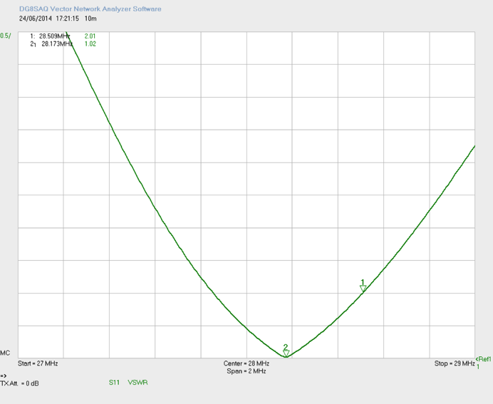
The 2:1 VSWR bandwidth is only 600kHz. The small bandwidth compared to a large conventional antenna is interesting in itself, and is discussed elsewhere on this site. It should be remembered a small magnetic loop of similar size to the EH antenna, will have a bandwidth about 5 times narrower. The subject of SWR and adjustment is trivial, so we move on quickly.
CFA and Poynting Vector Synthesis
The original crossed-field-antenna was based on a blatantly incorrect idea that an electric field has a duality of creating a magnetic field in empty space. There is no magnetic field between the plates of a capacitor. The CFA definitely falls into the category of fake antennas. The later EH antenna allegedly works by Poynting vector synthesis. A short simplified summary of what this is follows.
Exactly how a wire antenna (e.g., dipole) radiates is complex and open to debate. James Clerk Maxwell unified the forces of electricity and magnetism in the electromagnetic force. His famous four equations (condensed by Oliver Heaviside) are a cornerstone of physics, yet have been superseded by quantum mechanics. Unfortunately Maxwell died before his theories were proven and he knew nothing about antennas. To say the only way electromagnetic waves can be made is by a charge acceleration in a long wire is not a safe statement. Science is about understanding, so any theory can be challenged, or refined.
The mainstream explanation of how an antenna radiates is charge acceleration. Electricity doesn’t work by moving electrons, even Wikipedia makes this error; in an a.c. (alternating current) circuit the electrons don’t actually move on average, just jiggle about. It's the charge making up the current in the wires that actually moves (quickly). At UHF and above the electrons would have to move faster than the speed of light to get up the feed-line and back every time on every cycle. Its plain they don’t travel anything like so fast.
An a.c. current flowing in a wire causes acceleration of electrons and if the length approaches a half wavelength (quarter for a ground plane) then almost all the energy going in gets radiated as an electromagnetic wave. One of Maxwell’s students was John Poynting who developed the theory of how an electromagnetic wave moves. The E (electric) and H (magnetic) components at a distance from an antenna emerge as electromagnetic waves.
If we look at an antenna close up there are separate E and H fields, which are a by product and do not contribute to far-field radiation. The E and H fields drop off as a cube-law and beyond about 2π/λ range they are negligible. All we find is the electromagnetic wave. The near fields cannot be combined directly.
Basic reactive circuit elements generate phase shifts, so why not use them to generate alignment of the E and H fields? As said above, the EH antenna has a coil (inductor) which when tapped at the right position gives a low VSWR reading. So it looks like we just aligned our fields and generated a Poynting vector with a tiny antenna… but the local E + H fields are just a side-effect of charge acceleration, they do not cause far-field radiation!
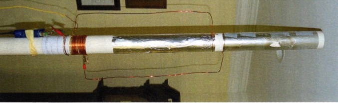
The tiny antenna consists of the coil feeding two cylinders. Here is a photo of an EH antenna for 28MHz as a reminder of how small it is (40cm long) and the construction.
If it’s working by Poynting vector synthesis, both the cylinders would be equally “active," i.e. changing their length would make a big difference. It’s also obvious both cylinders would be needed to generate the wavefront (“vector”) in the gap between them.
Whist changing the length of either cylinder makes the frequency shift, the upper cylinder has more effect. So to see if the antenna is working by Poynting vector synthesis, we remove the lower cylinder. Disconnecting the lower cylinder made the resonance increase from 28.0 to 31.6MHz. To get back to 28.0MHz extra turns were added to the coil.
With the lower cylinder in place, we get a field strength result to the inverted-V of -79.5dBm.
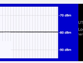
The graphic shows the KiwiSDR signal graph. Following results:
MMI-dipole vertical polarised = -79.5dBm. By co-incidence the same strength.
With the lower cylinder disconnected, and added coil turns to compensate:
Inverted-V = -80dBm
MMI-dipole vertical polarised = -79.0dBm
The antenna without the lower cylinder is marginally better. So the EH antenna does not work by Poynting vector synthesis. The lower cylinder is little more than a placebo which reduces the resonant frequency. The term “modified EH” above refers to one without the lower cylinder.
I did other tests with coils and plates, trying to adjust the phase by physically moving the components around. At no time was a peak in radiation noted. Also the “antenna part” was placed horizontally, and the radiation remained predominantly vertically polarised. These two tests together are further evidence the Poynting vector synthesis principle is invalid. Other variants like the “Super-T” also fail due to their belief in this easily dismissed theory, with performance over 10dB down compared to a horizontal dipole.
Despite Poynting vector synthesis theory being disproved, there is still an anomaly to investigate. The anomaly is described in the next section.
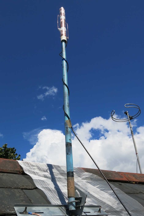
Here’s a photo of the antenna on the air in the summer.
Common Mode Current
The EH antenna and its forerunner Crossed-Field antenna are often accused of feed-line radiation and not the antenna itself. Prof. Maurice Hately (callsign G3HAT, originator of crossed field antenna) went to his grave arguing the point. The EH antenna and more recent Poynting vector antenna also fail to acknowledge common mode effects.
As concluded above the EH antenna does not work by Poynting vector synthesis. The most likely way it does work is by radiation from the coax between the antenna and transmitter. The term “common mode” means a current is flowing through a ground or alternative path, in this case the outside of a coax cable. Is the outside of the coax doing the radiating with the EH antenna, not what we see as the antenna? I decided to answer this question but came up with some surprising results.
After making many EH antennas and hours tapping off coils, I never measured a reduction to near zero of common mode (CM) current. My measurement instrument is a simple transformer current meter. The promotors of the EH antenna claim that common mode current can be minimised by moving the coil tap; I find it cannot.
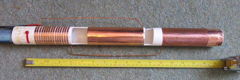
Having seen from previous tests that the lower cylinder was doing nothing, a new design with a flat grid was made. The construction allows easy changes of length and amount of coil turns.
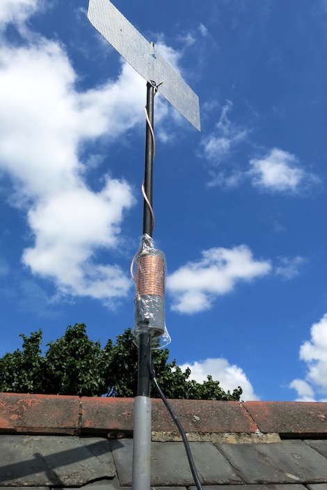
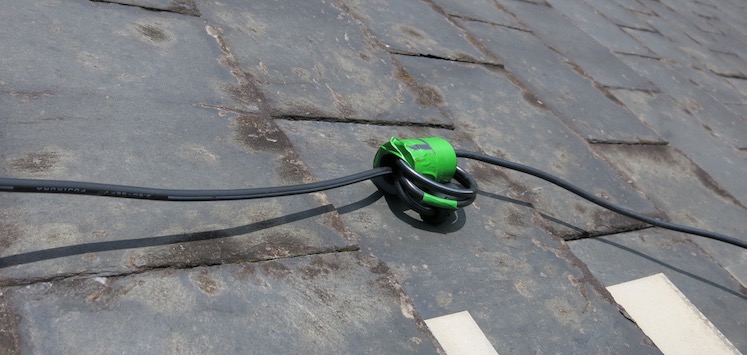
A high impedance coaxial choke (balun) is placed a distance down from the top section to stop common mode current at a defined position. The choke stabilises the tuning to allow reliable adjustment and also marks the edge of the radian-sphere as defined in the Chu-Wheeler ESA formulas. In effect, it “cuts” the coax to allow different lengths to be tested easily by shuffling the turns through the ferrites.
One choke used was made of four FT140-61 ferrite rings. Ferrite 61 offers a good combination of inductive and resistive impedance above about 20MHz. The RG58 cable was wound 4 times through a stack of 4 rings. Effectiveness of the choke was confirmed by the VSWR reading on the analyser staying unchanged when the cable below the choke was touched or connected to anything. A simple current-clip meter was also used to check the amount of common mode current
Several tests were made on the length of cable between the top section and choke. It was found for coax lengths approaching 1/4λ between the top section and choke, an air cored choke could be used. But signal results for that arrangement were no better than for much shorter cable lengths. For shorter lengths than 1/4λ high impedance ferrite chokes had to be used because air core didn't have enough impedance to stabilise the tuning.
Feed-line length reduction
It was decided to begin with 1.5m of cable and antenna length of 1.0m. The frequency used for all these tests was near 28.0MHz (λ/4 = 2.7m). So the starting point comparison was for a total length close to a quarter wave. The KiwiSDR S-meter extension was used to obtain a trace from the inverted-V:
-83dBm
It was found rotation of the paddle and position of the coax on the roof made no difference to the signal. Reducing the cable to 1.0m produced:
-83dBm
Then the paddle was moved down to 30cm and the cable reduced to 0.6m, for a total length of 1.30m:
-83dBm
Next at 100cm, which is 9% of a wavelength:
-86dBm
Conclusions on common mode current
The active length of the antenna was reduced from 2.5m to 1.3m with no measurable reduction in signal. This is 60%, which should have a large effect according to conventional theory. Reducing to 0.1λ (0.11m) for the whole antenna did start to reduce signal. This test reduced the coax cable from 150cm to 60cm (2.5x) with no effect on far-field radiation. This indicates common mode current is not the primary source of radiation, and is at odds with conventional theory. Having repeated the test several times, I suggest those “experts” who sit behind a NEC2 simulator should build the antenna and ignore what the computer says.
The result that the coax can be reduced so far whilst not reducing performance is a potentially important finding.
Conclusions on EH antennas
1 It does not perform so well as a conventional full size antenna
2 The radiation mostly doesn’t come from the coax cable, but from the high voltage plate/cylinder
3 Poynting vector synthesis is an incorrect concept
These findings are controversial because of the theory antennas can only radiate by charge acceleration caused by RF current in wires. There is evidence to suggest alternative forms of charge acceleration can generate electromagnetic radiation. This grain of truth is buried under lots of prejudice and politics.
Having probably disproved the common mode current theory, there are some other points to investigate; Where does the 7dB loss compared to a conventional antenna happen?; The bandwidth is unexpectedly wide for such a tiny antenna.
To round off this page, a look at the latest work of the proponents of the EH antenna. It is now renamed the “Poynting vector antenna” PVA.
Poynting Vector Antenna (PVA)
I constructed a PVA for the 20m band (14MHz).
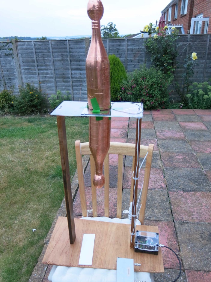
This antenna whatever I did to it performed poorly, very “dead” and lacking in background noise. I didn’t try it on the roof, but in the loft it was 2 or more ’S’ points below the external wire antennas. The one with bottles covered in copper is similar to those shown on the site of SM6DCO (Conny).
It was found the loading coil (just visible in the photo) and balun (in the transparent topped box) got warm with only 10W power. Also, connecting the top “bottle” at the end produced the same SWR, and the same background noise. These experiments indicate the antennas are little more than radiating tuned circuits, and based on fanciful theories with a lack of rigorous measurements. So again the Poynting vector synthesis is disproved, and we see “anything works” with antennas. However, not everything is lost, as there is still much research to be done in small antennas!